Thinking it was similar to building one had normal switches, I tried to build my first keyboard with hot swappable sockets. I was so wrong. Not only could I not find build logs of anyone who has built one, but soldering wires to the Kalih hot swappable sockets was so much harder. So please read on if you're as clueless as I was.
There are many build logs out there so I'll distill what I thought was helpful and share some mistakes I've made to prevent you from repeat them before continuing with the build log.
Helpful but not obvious
Soldering the copper tape first
Start with soldering the copper tape and not the wires, but leaving the top most switch unsoldered. The topmost switch should be soldered together with the wire.
I made a mistake of soldering the diodes first because most guides suggested it. To my horror, I found out later that the copper wire cannot be wrapped around the hot swappable sockets. So I had to sneak the copper tape under the existing wires, which probably added at least an hour or two to my build time.
Solder the diode as close to the socket as possible
None of the guides I read told me to do this even though some images I've seen hinted that. Or maybe everyone already knew that except me, a soldering noob.
Soldering the diode close to the socket (or switch) ensures that the diode doesn't move around too much. There's also less of a chance that the row wire would touch another.
Understand what you're building
There're many guides out there and some have subtle differences of how they wire the thumb cluster or the materials they use. Since it's my first time soldering a keyboard, I just followed a mishmash of the popular guides. I'm glad it worked out but I just didn't know what the options were and the tradeoffs I was making.
Took me a while to understand how the wiring allows the controller to know which key was pressed. So even though I followed the popular wiring guide at https://github.com/abstracthat/dactyl-manuform, I might not need to in the future. The QMK guide to split keyboard also suggested an alternative wiring to connect the 2 controllers which I didn't know existed until I flashed the controller.
Wiring Diagram
Not drawn to scale but hopefully it's clear. It's an svg file so you'll be able to zoom in as needed. I found that most diagrams don't have the reset switch and they only show one side at a time.
To understand this diagram, it is drawn from the perspective of the underside of the keyboard. The brown and black rectangles represent the diodes and the direction they need to be in for the current to flow the right way. I used elite-c's because I've read that pro micros are fragile but they work as well.

Building the keyboard
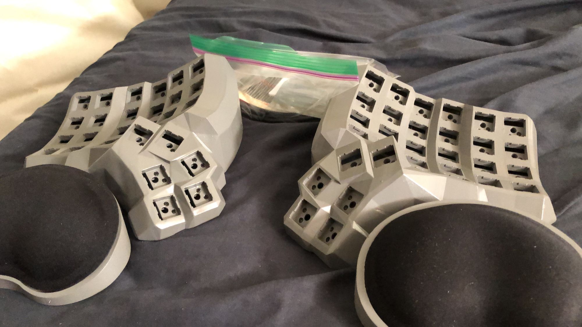
Materials and Tools
- 3D printed case with hot swappable kalih switches, base, wrist rests and elite-c holder printed by reddit user crystalhand
- 2 Elite C controllers
- 2 3.5mm TRRS sockets
- Reset button switch
- 64 Diodes (a few spare would be handy just in case)
- Solder core
- Solid core copper wires (from ethernet cables)
- 5mm width copper tape
- Soldering Iron
- Soldering Iron Tip Cleaner (An old wet cloth or sponge will do as well)
- Pliers
- Tweezers
- Digital Multimeter (optional, but useful for debugging and troubleshooting if something goes wrong)
- Screws, nuts and screwdrivers (optional, only needed if you want to cover the bottom or to attach the printed wrist rests)
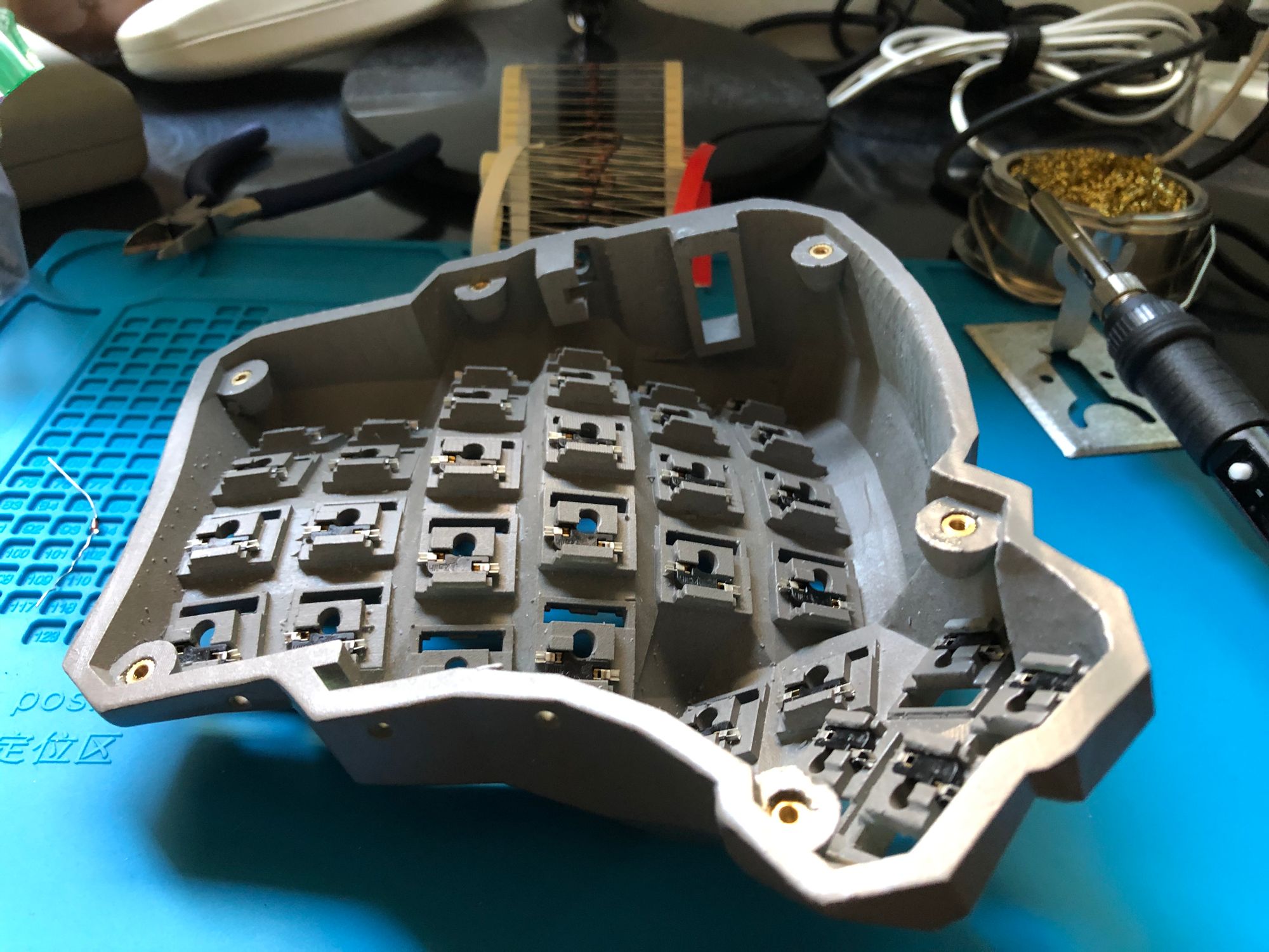
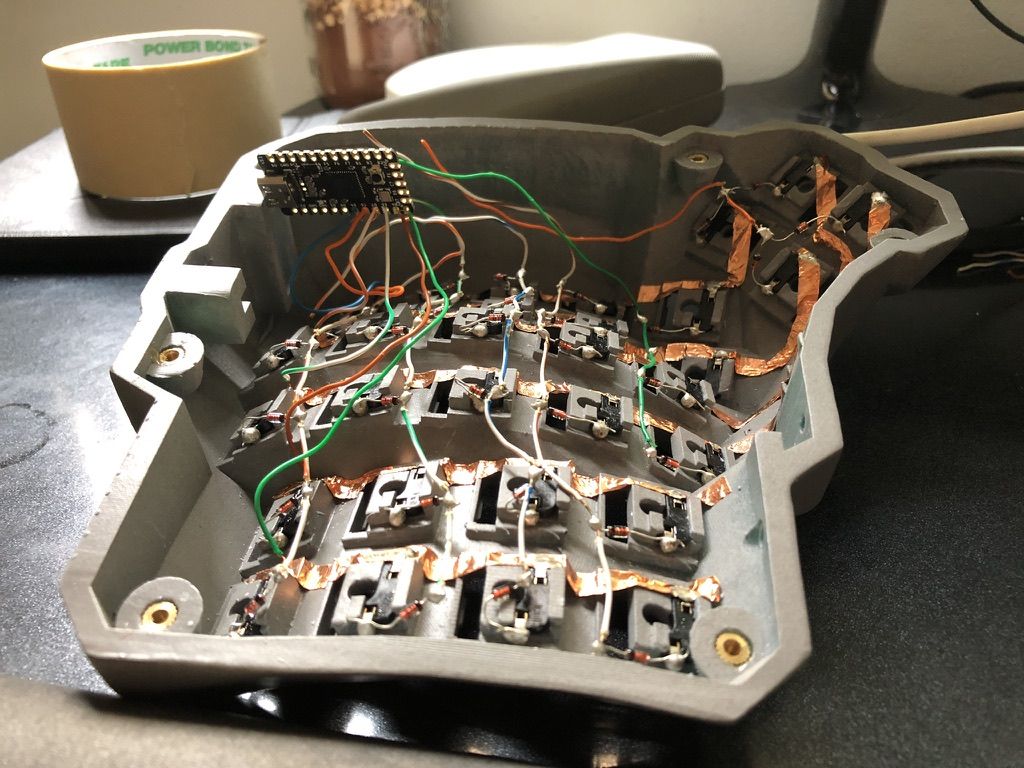
Soldering the connections
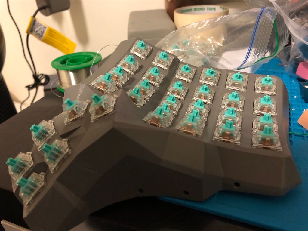
I started with the diodes because I wasn't expecting to use copper tape later. So don't repeat my mistake and start with the copper tape instead. I was building the 5x6 version of the dactyl manuform so it wasn't too difficult finding wiring diagrams for it. As said in other build logs, winding the diode wire around the node would help. However, it'll be trickier to wind it around the hot swappable socket.
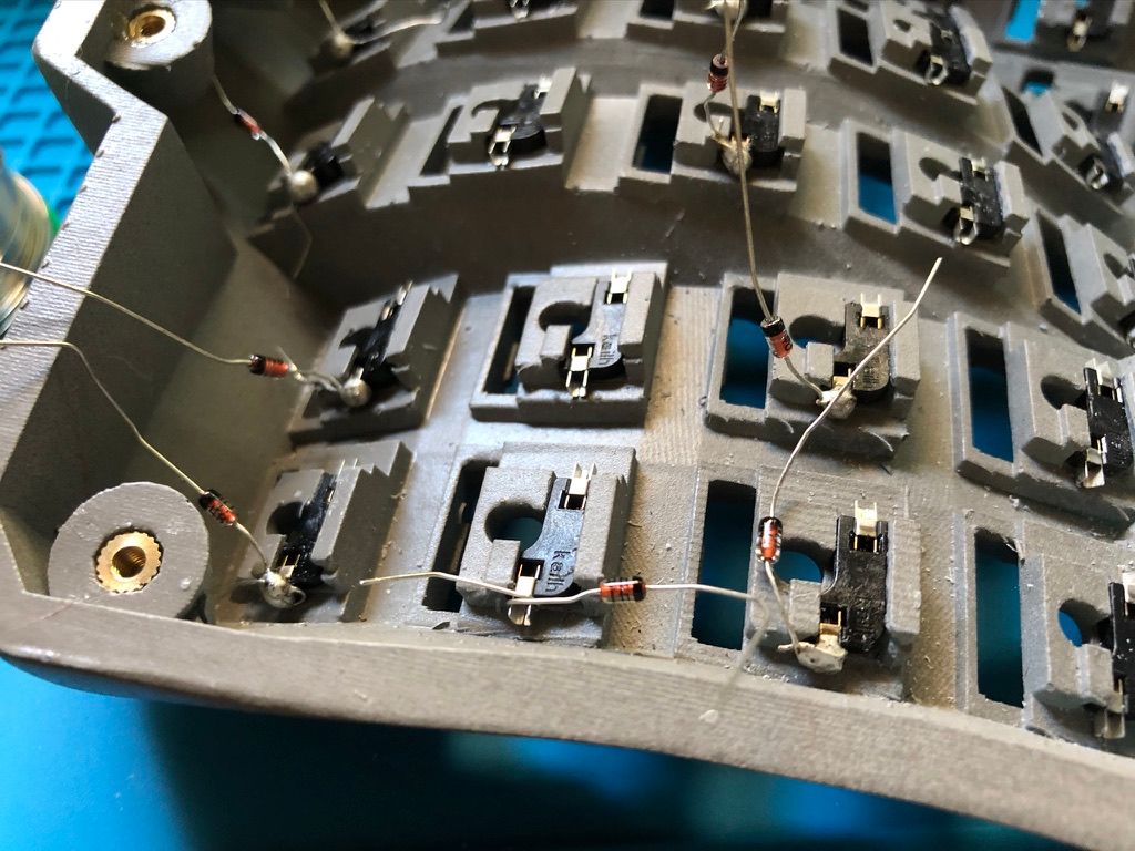
When you get to the corners, you'll likely have to use the tweezers to finish the job.
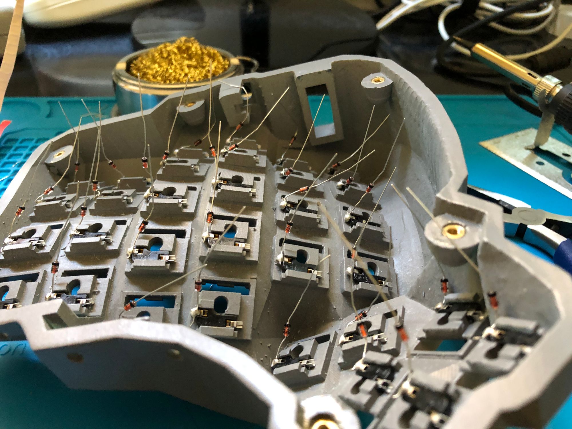
As you can see, some diodes are pretty far away from the sockets, which I'll live to regret later on.
Since I've started on the diodes, I continued by soldering the row wires. After removing the individual wires from the ethernet cable, I got to work. The wire stripper I got was too big so I had to return it, leaving the only other option which was to use the soldering iron to melt the insulation of the wires. That didn't leave me with the cleanest cuts but it worked.
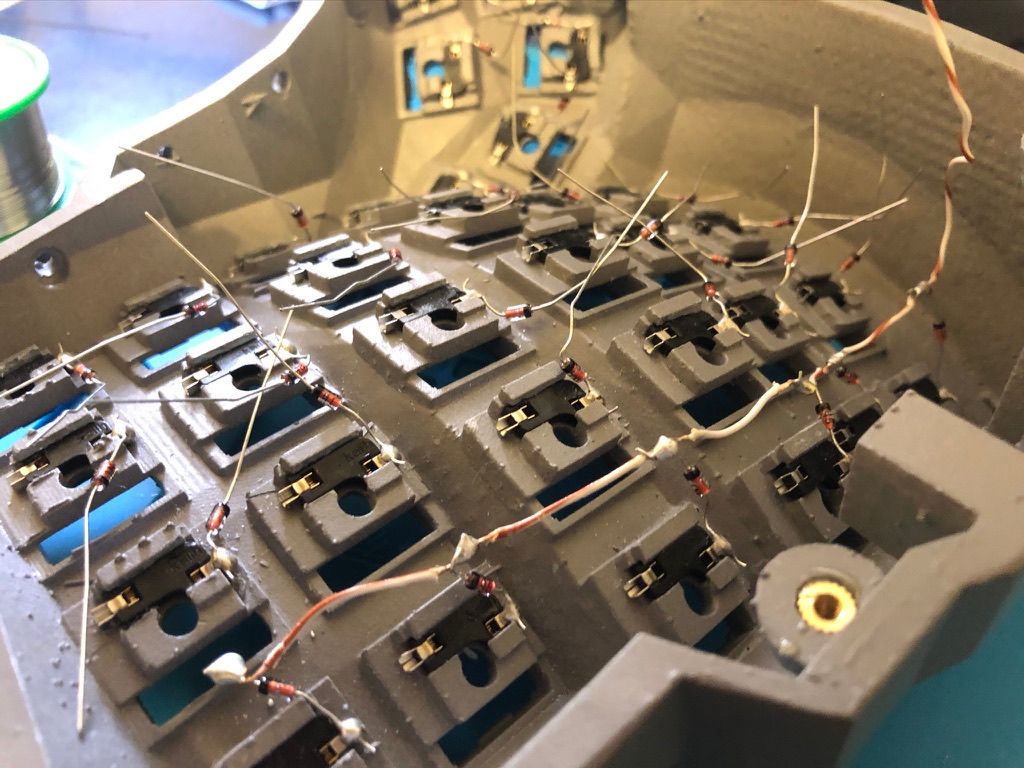
Now for the columns! I assumed I could wind the wire around the socket like all the guides for the switches mentioned but I was clearly mistaken. The copper wires were a little thicker than the diode wires, which resulted in me being unable to wind them around the sockets. I saw some guides that used copper tape so I ordered them online.
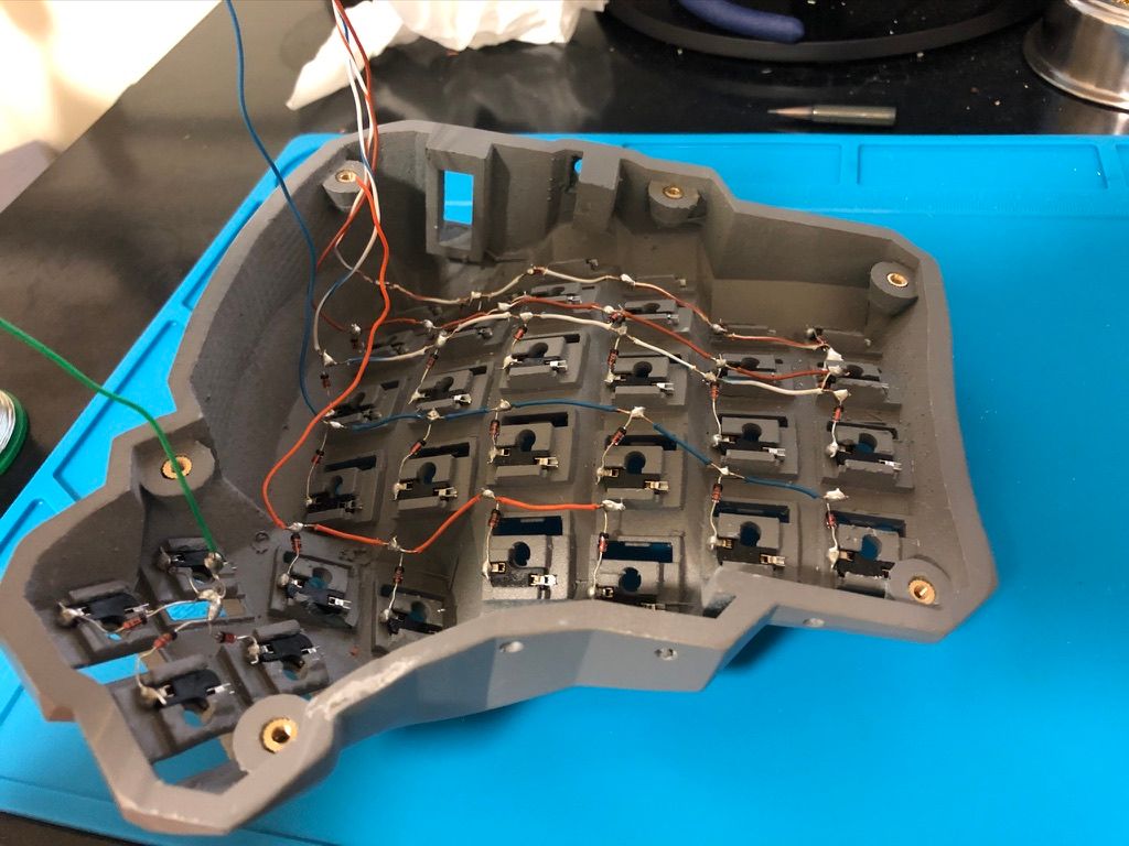
After waiting for a couple of days for the copper tape to arrive from a local hardware store, I realised that it'll be difficult to get the tape under the wires. After much patience and perseverance, it was complete.

I found the thumb cluster to be insanely difficult with the copper tape so a tip is to plan where you're going place the tape.
Soldering the wire to the copper tape was also tricky because don't forget, I couldn't wind it around the socket. What I found helpful was to tape one side of the wire such that pressure was applied to the end of the wire in contact with the tape. I know it sounds vague so hopefully this next photo would help.
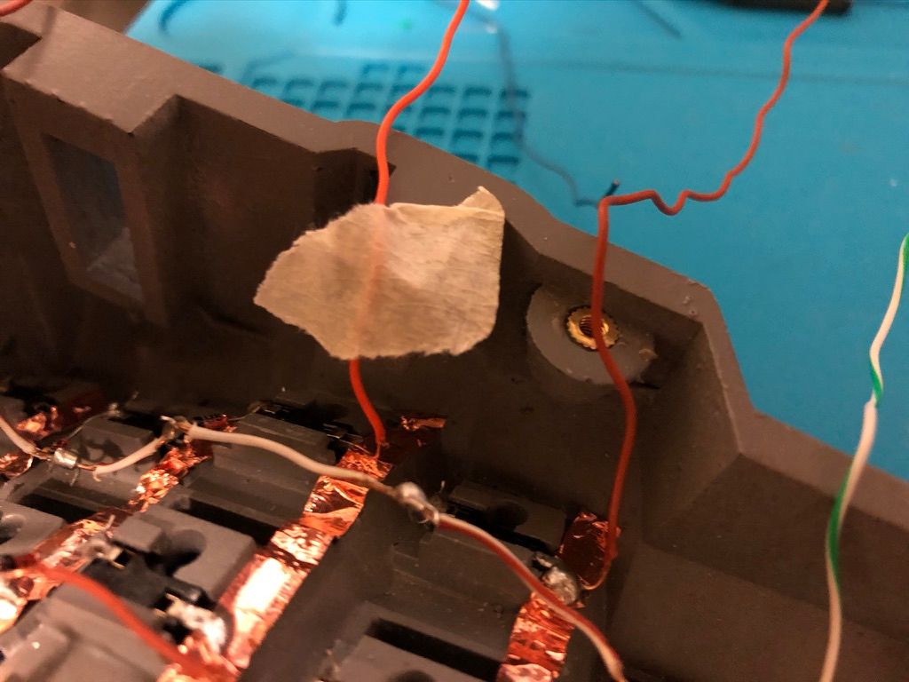
The exposed end of the wire was bent to be in contact with the socket and copper tape at the same time. With the masking tape helping it stay in place, soldering was more manageable.
Soldering the components
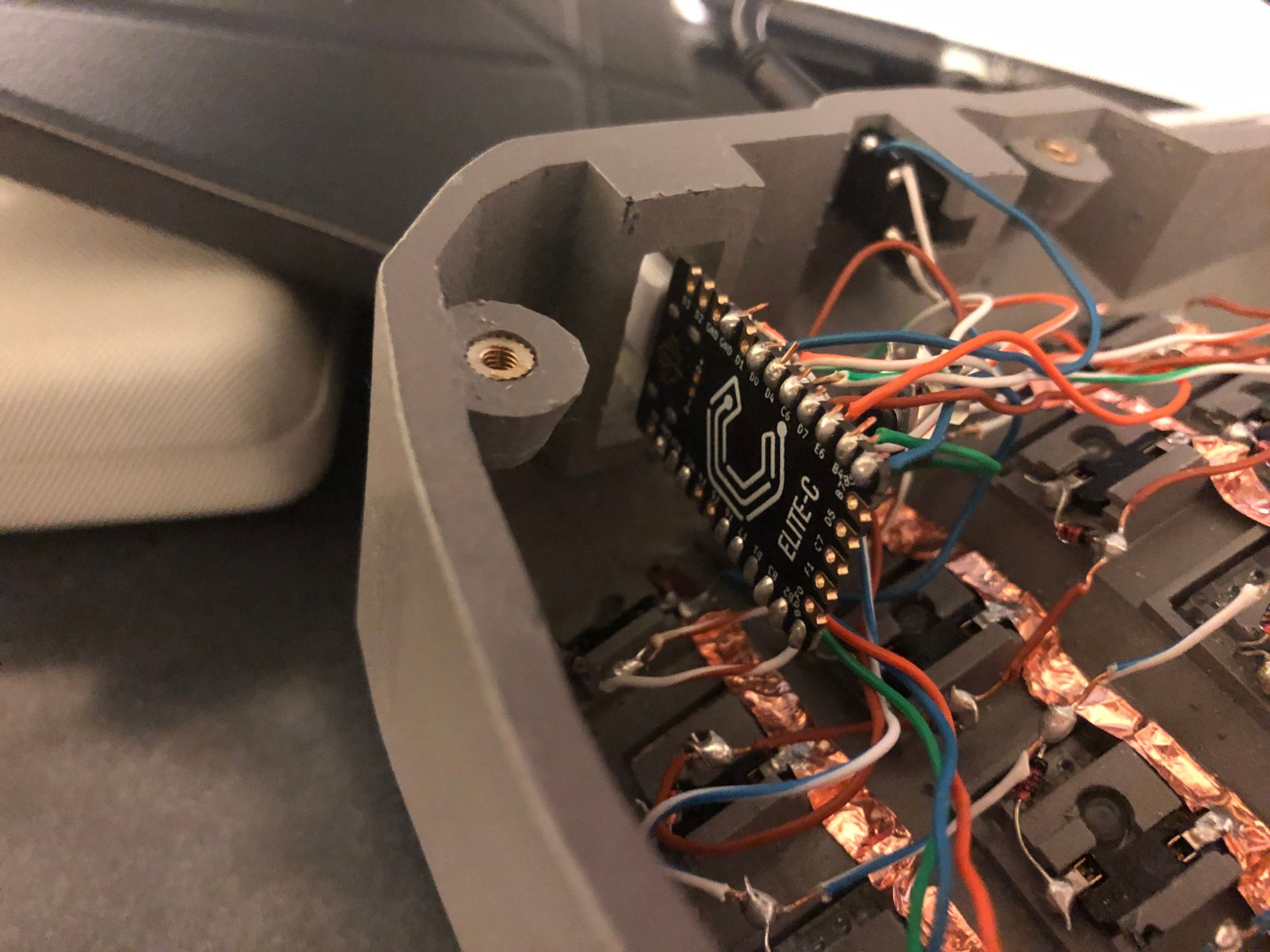
Once the rows and columns are complete, it was time to solder the components. Before soldering to the elite-c, you'll need to wind the exposed end of the wire around the side. It's not that clear but the wire needs to enter from the top and curl at the bottom because the soldering will be done below the controller. Ensure that this is done for all wires so it's consistent.
One mistake I made here was to not give enough slack for the wires so I had to solder 2 wires together because I realised one was too short. If you have the holder for the elite c, ensure that you have enough slack so that elite c can peek out through the cavity for the holder to fit.
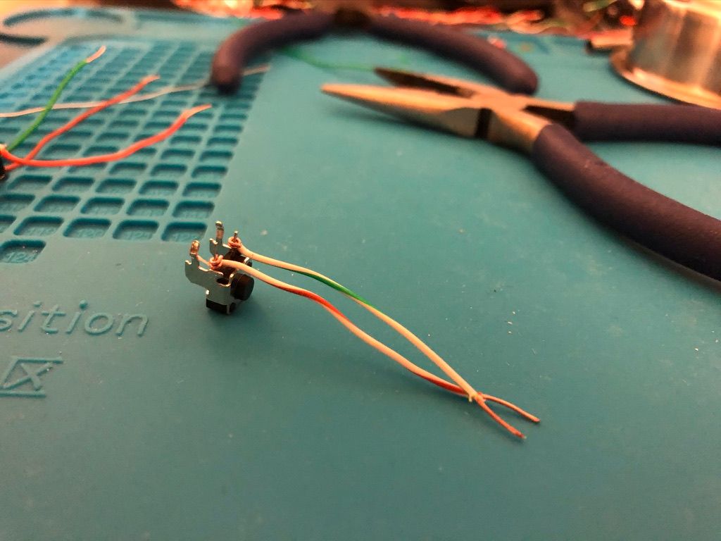
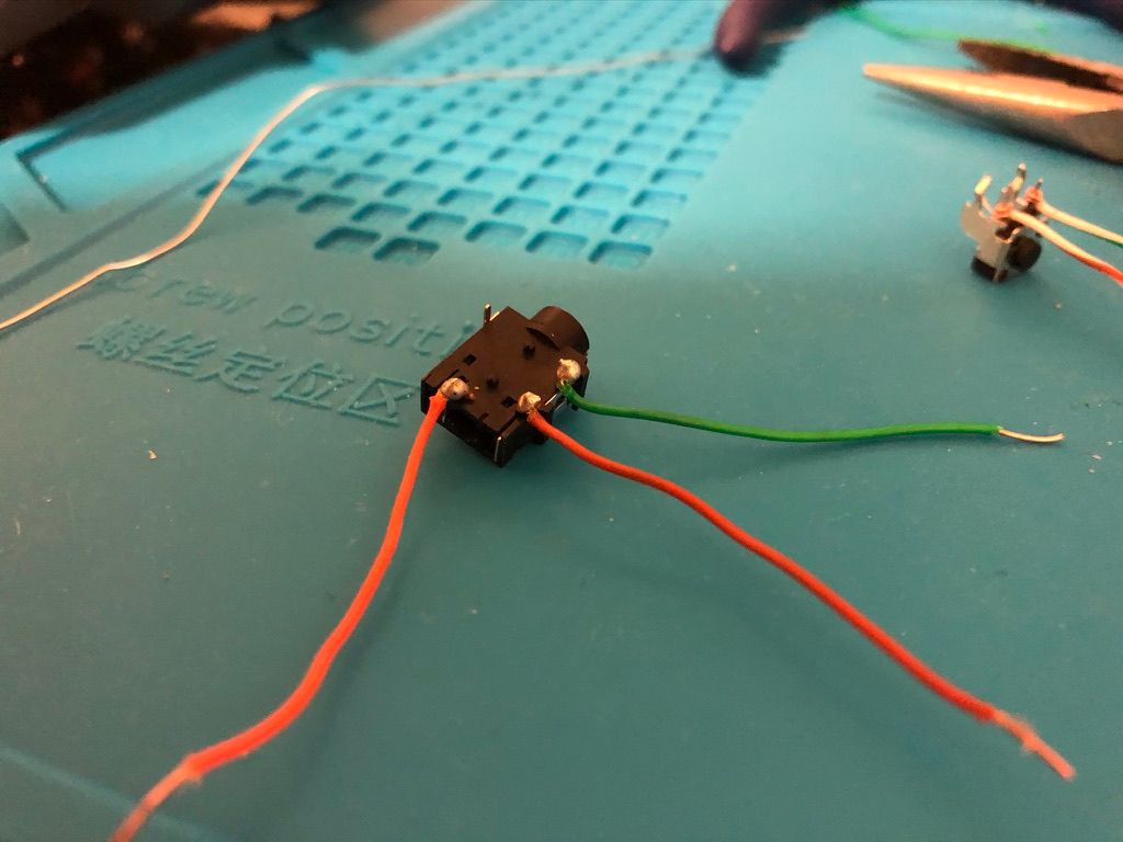
Quite a few guides would suggest a specific GND position for the TRRS wire but any one of them would do as long as it's labeled GND. Since I was going to solder the reset switch to GND and RST, I used the GND adjacent to RST for the reset switch.
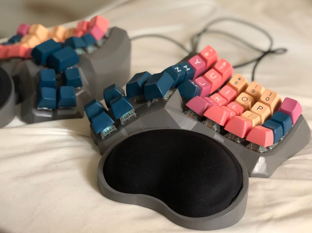
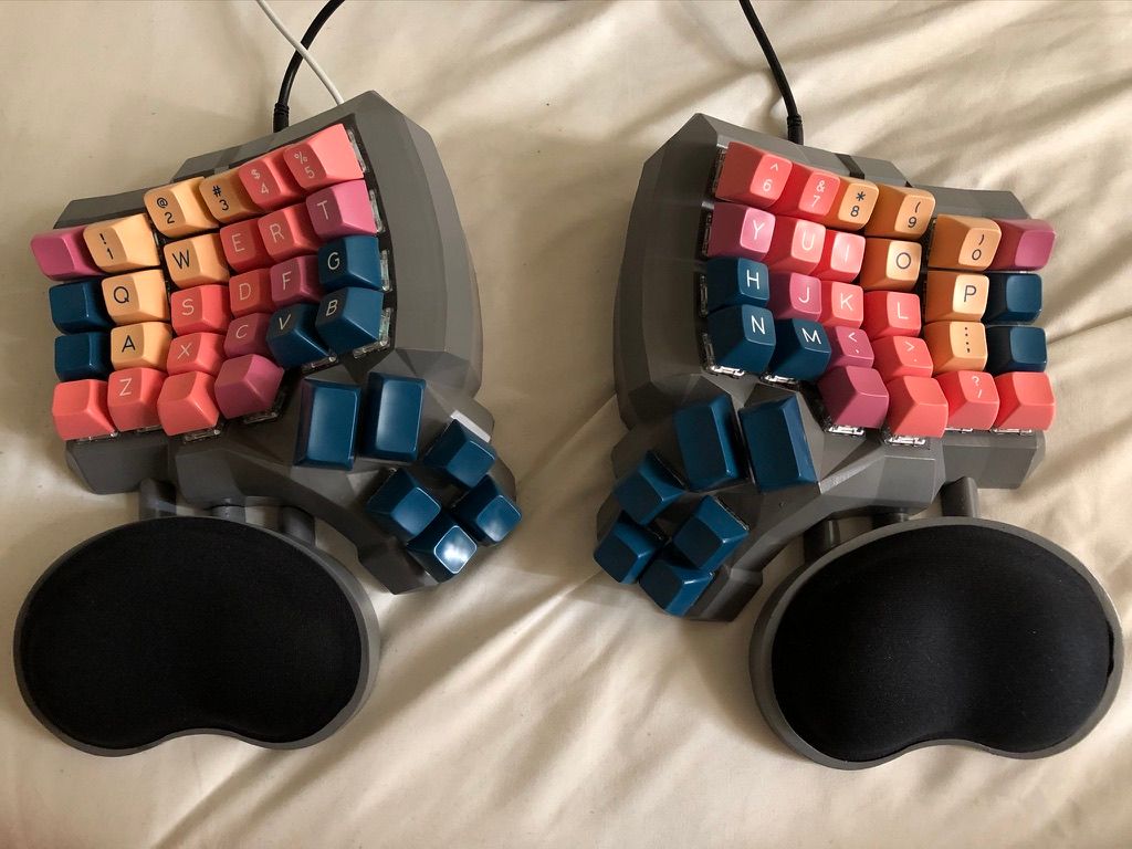
And before I knew it, I was finally done! Now came the easiest part, adding the switches and keycaps.
Flashing the controller
The open source program QMK is what you're looking for to configure it. For the first flash, I just got the defaults working so I could test out if any keys weren't working. Following the instructions, I used homebrew to install it on my mac. It was surprisingly easy to install.
brew tap qmk/qmk
brew install qmk
QMK is well documented and I'd advise you to read the documentation before continuing. After reading the documentation, I flashed the left side first and connect the right side for the default settings. And it seemed everything was going well.
It turned out I celebrated too early. After testing the keyboard at qmk, I found 4 keys that weren't working. Immediately, I rushed to get the multimeter to diagnose the issue. Finding out that the circuits were working fine which meant no more soldering, I heaved a sigh of relief. It was the switches' pins that were bent. After straightening them out, it was perfect.

After spending some time tinkering with the online configurator, I arrived with one which mimicked the layout of my ergodox. Don't worry if you don't know how to use a text editor or read C. The online QMK configurator and toolbox doesn't require you to use any text editor.
And after pressing the reset button followed by one final flash, that's it!
A few days in and I'm pretty sure I'll be using this keyboard for a long time to come.